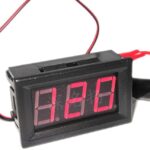
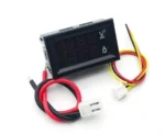
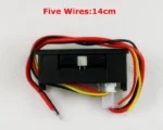
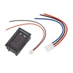
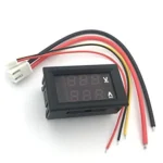
This is a 0.28′′ 5 wire digital dual red LED ammeter with 100V and 100A DC current. This metre has a 0.1-volt resolution and can measure up to 100 VDC.
It’s important to remember that this metre has two wiring harnesses. One harness, which consists of two poles with a RED and a BLACK lead, powers the metres. The voltage and current magnitudes are shown simultaneously on the same screen, making it portable and small in size.
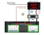
The voltage range for this supply is 6 VDC to 30 VDC. It is feasible to utilise the same power supply, however it appears to have an impact on the amp metre reading. This is a different power supply that is isolated from the source. The three-wire harness is utilised for a ground that is connected straight to the load’s supply ground or battery.
Note: There are two different wiring variants (i.e. yellow wire and Green wire ) with the same working functionality is available which will be shipped randomly. Use the following guidelines according to your version.
CASE 1: Onboard Wiring Instructions for “Yellow” Wire connection
1. Thin Red Wire (VCC): positive pole of power supply input (4.5-30V)
(Note: if the measuring signal is less than 30V and the power is adequate, can be the power supply of module)
2. Thin Black Wire (GND): the negative pole of power supply input (4.5-30V, common ground with measuring signal)
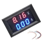
3. Green Wire (VIN): positive pole of measuring signal input (0-100V)
4. Thick Red Wire (I+): positive pole of current input (series connect on the power supply cathode)
5. Thick Black Wire (I-): the negative pole of current input (series connect on the power supply cathode)
Connection Diagram:
Note1 : If the input voltage is more than 5V, then, please use a buck converter.
Note2 : This Product Does Not include a shunt.
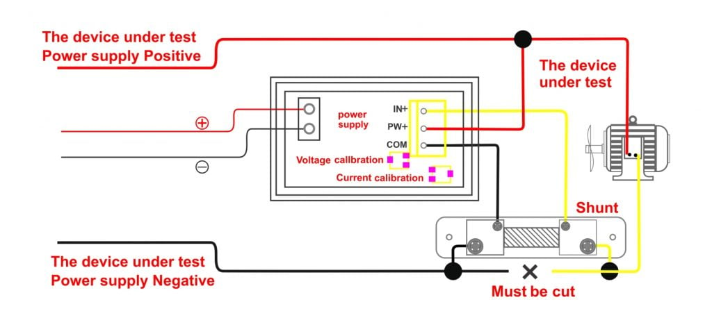
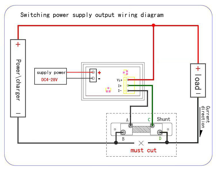
CASE 2: Onboard Wiring Instructions for “Green” Wire connection
(The current range of 10A requires the external shunt connection process)
1. Connect the lines which are not connected well, and do not touch other places.
2. The shunt is connected to the negative pole of the measuring system (the shunt itself does not distinguish the direction, and the connection is fixed to the two large screw holes in the distributor.
3. According to the current direction, the green line (+) and the black line (-) of the three lines are respectively screwed on the two small screws of the shunt.
4. Connect the red line of the three lines to the positive pole of the measuring system.
5. The power supply line in the two lines is connected to the appropriate power supply (and the voltage between the black lines in the three lines. It is suggested to be connected to the 12V, at the same time, the electric power black lines in the two lines are wrapped with insulating tape, so do not encounter other places, so as not to cause a short circuit).
6. The above 1-5 steps are suitable for the use of common ground; for independent power supply occasions, the red and black lines of power supply in two lines are respectively connected to both sides of the positive and negative poles of the power supply (the power supply voltage <28V, suggested to be about 12V).
Connection Diagrams:

Features :
- It measures up to 100V and 100A DC.
- Very handy and small in size.
- It requires a power supply of 5V.
- 100% Brand new and high quality.


Reviews
Clear filtersThere are no reviews yet.