-32%

 Power Supply
 Electronic Components
 Ai Thinker ESP Wifi Modules
 Current Sensors
 Drone Parts
 IoT & Wireless
 E-Bike Parts
 Mechanical components


Hurry and get discounts on all Raspberry Products up to 20%
IBOTS1000
₹78.00 Original price was: ₹78.00.₹53.00Current price is: ₹53.00.
Free
₹75 for parcels below 1 Kg and ₹100 for parcels weighing between 1 Kg to 2 Kg.
2-3 Days
₹75
₹125 for parcels below 1 Kg and ₹175 for parcels weighing between 1 Kg to 2 Kg.
2-3 Days
₹125
₹250 for parcels below 1 Kg and ₹325 for parcels weighing between 1 Kg to 2 Kg.
2-3 Days
₹250
Our courier will deliver to the specified address
2-3 Days
Rs. 99
Payment Methods:
1. Order the Product and Specify the Delivery Method
2. You Will Receive an Order Confirmation Message
3. Wait for Your Order to Arrive
4. Pick up Your Order at The Checkout Area
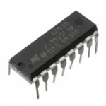
The integrated circuit (IC) L293D PowerDIP-16 Stepper Motor Controller/Driver is a twin H-bridge motor driver. Because they create a higher-current signal from a low-current control signal, motor drivers function as current amplifiers. The motors are driven by this signal with a greater current.
The device is a monolithic integrated high voltage, high current, four channel driver that can control switching power transistors and inductive loads, including relays, solenoids, DC, and stepping motors, at normal DTL or TTL logic levels. In order to facilitate usage as two bridges, every pair of channels has an enable input. Internal clamp diodes are present, and the logic is supplied with a second supply input that permits operation at a lower voltage.
Up to 5 kHz of frequency switching applications are appropriate for it. The L293D is put together in a sixteen-lead plastic box with four centre pins that are utilised for heatsinking. The L293DD is installed on a 20-lead surface mount with eight central pins that are utilised for heatsinking and connection.
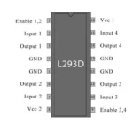
Two integrated H-bridge driver circuits are present in L293D. Two DC motors can be driven concurrently in both forward and backward directions in its typical mode of operation. Input logic at pins 2 & 7 and 10 & 15 can control the motor operations of two motors. The appropriate motor will be stopped by input logic 00 or 11. It will rotate in clockwise and anticlockwise directions, respectively, according to logic 01 and 10. For the two motors—corresponding to enable pins 1 and 9—to begin running, they must be high.
The related driver is enabled when an enable input is high. The outputs then turn on and operate in tandem with their inputs. Similar to this, the driver is disabled and its outputs are turned off and in the high-impedance state when the enable input is low. In positive-supply applications, they are intended to drive inductive loads like relays, solenoids, dc, and bipolar stepping motors, in addition to their high-current/high-voltage counterparts.
Note: Depending on availability, the image may differ from the actual product in terms of the manufacturer or brand name.
Features:
Only logged in customers who have purchased this product may leave a review.
Categories
Useful Links
Useful Links
 Power Supply
 Electronic Components
 Ai Thinker ESP Wifi Modules
 Current Sensors
 Drone Parts
 IoT & Wireless
 E-Bike Parts
 Mechanical components
No account yet?
Create an Account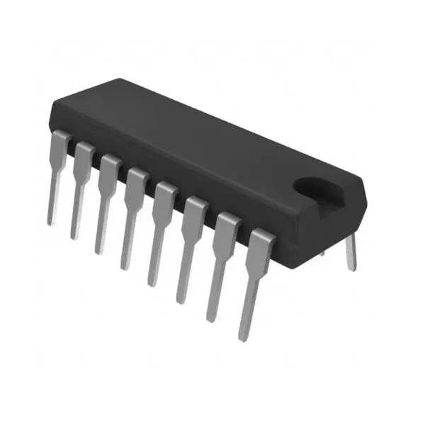
Reviews
Clear filtersThere are no reviews yet.