Ai Thinker NodeMCU-32S-ESP32 Development Board Original price was: ₹940.00.Current price is: ₹810.00.
Back to products
Ai Thinker ESP-12F ESP8266 Serial WiFi Module Original price was: ₹250.00.Current price is: ₹179.00.

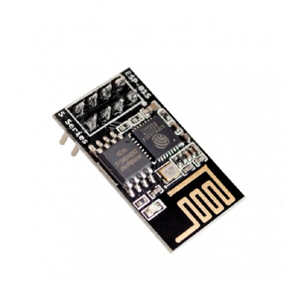
Ai Thinker ESP-01S ESP8266 WiFi Module

  • 1MB (8Mbit) Flash size.
  • Very competitive price
  • AP, STA, AP+STA modes available.
  • Very simple AT commands, easy to use.
  • Internal LWIP interface.

Note

  • Within India, 3 – 4 days lead time with 100% advance
  • For imports, 15 days lead time with 50% advance

IBOTS's 10th Anniversary Sale

Hurry and get discounts on all Raspberry Products up to 20%

IBOTS1000

Original price was: ₹299.00.Current price is: ₹215.00.

Available on backorder

Available on backorder

  • Pick up from the IBOTS Store

Free

  • Delivery Charges: Tamil Nadu

₹75 for parcels below 1 Kg and ₹100 for parcels weighing between 1 Kg to 2 Kg.

2-3 Days

₹75

  • Delivery Charges: Other South India

₹125 for parcels below 1 Kg and ₹175 for parcels weighing between 1 Kg to 2 Kg.

2-3 Days

₹125

  • Delivery Charges: North India

₹250 for parcels below 1 Kg and ₹325 for parcels weighing between 1 Kg to 2 Kg.

2-3 Days

₹250

  • Courier delivery

Our courier will deliver to the specified address

2-3 Days

Rs. 99

  • Warranty 1 year
  • Free Returns Policy

Payment Methods:

1. Order the Product and Specify the Delivery Method

2. You Will Receive an Order Confirmation Message

3. Wait for Your Order to Arrive

4. Pick up Your Order at The Checkout Area

Description

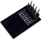
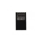
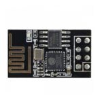
The Ai Thinker ESP-01S is a WiFi module based on the ESP8266 microcontroller from Espressif Systems. This module is widely used for adding WiFi connectivity to various projects due to its compact size and cost-effectiveness. Here’s an overview of the Ai Thinker ESP-01S ESP8266 WiFi module:

Key Features

  1. Microcontroller:
    • ESP8266: A low-cost, low-power microcontroller with integrated WiFi capabilities.
  2. Memory:
    • Flash: Typically 1MB or 2MB.
    • SRAM: 64KB of instruction RAM and 96KB of data RAM.
  3. Wireless Connectivity:
    • WiFi: 802.11 b/g/n, supports WiFi Direct (P2P), soft-AP, and TCP/IP protocols.
  4. GPIO Pins:
    • Digital I/O: 2 GPIO pins, can be used for digital input or output.
    • UART: 1 UART interface, used for serial communication.
  5. Power Management:
    • Operates at 3.3V.
    • Low power consumption, suitable for battery-powered applications.
  6. Antenna:
    • Integrated PCB antenna for WiFi communication.
  7. Dimensions:
    • Very compact, typically around 24.8mm x 14.3mm, making it suitable for space-constrained applications.
  8. 1MB (8Mbit) Flash size.
  9. Very competitive price
  10. AP, STA, and AP+STA modes are available.
  11. Very simple AT commands, easy to use.
  12. Internal LWIP interface.
  13. Four pins interface, VCC-3V3, GND, TXD, and RXD. Two extra GPIOs can be used.
  14. AT commands firmware. New IC ESP8266ex

Pinout Description

  1. VCC: 3.3V power supply.
  2. GND: Ground.
  3. TX: Transmit data (UART).
  4. RX: Receive data (UART).
  5. CH_PD: Chip enable pin (should be pulled high to enable the chip).
  6. GPIO0: General-purpose I/O pin 0.
  7. GPIO2: General-purpose I/O pin 2.
  8. RST: Reset pin (active low).

Common Applications

  • IoT Projects: Connecting sensors and actuators to the internet.
  • Home Automation: Creating smart home devices.
  • Wireless Data Logging: Sending data to a server or cloud.
  • Remote Control: Controlling devices remotely via WiFi.

Getting Started

  1. Setup the Development Environment:
    • Arduino IDE: Install the ESP8266 board support through the Boards Manager.
    • Espressif SDK: For more advanced development, you can use the ESP8266 SDK.
  2. Connecting the Module:
    • Use a USB-to-serial adapter to connect the ESP-01S to your computer.
    • Ensure proper voltage levels, as the module operates at 3.3V.
  3. Flashing Firmware:
    • Use the Arduino IDE to write and upload code to the ESP-01S.
    • Select “Generic ESP8266 Module” as the board in the Arduino IDE.
  4. Power Supply:
    • Ensure the module is supplied with a stable 3.3V power source.
    • Do not exceed 3.3V on the power pins to avoid damaging the module.

Tips

  • Make sure to pull the CH_PD pin high to enable the module.
  • Use a voltage divider or level shifter for UART communication if using a 5V system.
  • Handle the module carefully to avoid damage from static electricity.


Customer Reviews

0 reviews
0
0
0
0
0

There are no reviews yet.

Only logged in customers who have purchased this product may leave a review.