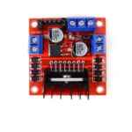
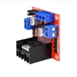
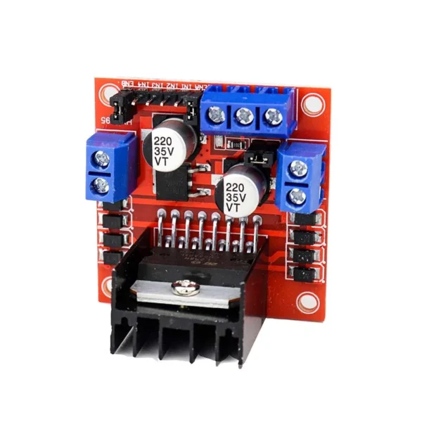
It contains an onboard 5V regulator that it may feed to an external circuit, and it makes use of the well-known L298 motor driver IC. Up to four DC motors can be driven by it, or two DC motors with speed and direction control.
This motor driver is ideal for controlling motors from microcontrollers, switches, relays, and other electronic devices, making it ideal for robotics and mechatronics projects. Ideal for powering DC and Stepper motors in robotic arms, line-following robots, micro mice, and other applications.
H-bridges are typically used in controlling motors speed and direction but can be used for other projects such as driving the brightness of certain lighting projects such as high powered LED arrays.
Pulse Length One way to adjust an electrical pulse’s duration is by modulation. Try to visualise the brush of a motor as a water wheel and the electrons as the water droplets moving. Water running over the wheel at a consistent rate would represent the voltage; the more water flowing, the higher the voltage. Because motors are rated for specific voltages, they might be harmed by excessive voltage application or abrupt voltage drops intended to slow the motor down. PWM follows. Using the water wheel example, imagine that water is flowing into it continuously but in pulses. The water wheel will turn more quickly with longer pulses and more slowly with shorter pulses. PWM control will make motors far more dependable and long-lasting.
Ensure that the Arduino, power source, and motor controller are all connected to one another.
If you do not wish to control PWM features, then you do not need the PWM Pins.
The Arduino code sketch is pretty straightforward. Since there isn’t a library for the L298N Dual H-Bridge Motor Controller you just have to declare which pins the controller is hooked to.
The “int dir(number)Pin(letter)”‘ pins can be connected to any available digital pin you have available, as long as you declare the correct pin in your sketch. This makes the L298N Dual H-Bridge Motor Controller very versatile if your project is using a lot of Arduino pins.
The int“speedPin(letter)” pins need to be connected to a PWM pin on the Arduino if you want to enable speed control through PWM.
As a quick cheat I have included a list of PWM pins for the main two types of Arduino’s I use:
- AT MEGA – PWM: 2 to 13 and 44 to 46. Provide 8-bit PWM output with the analogWrite() function.
- UNO – PWM: 3, 5, 6, 9, 10, and 11. Provide 8-bit PWM output with the analogWrite() function.
Features:
- 2 amps per motor is the maximum motor supply current.
- Every motor has a current sensor.
- Heatsink to improve efficiency.
- LED power-on indicator.
- Chip for double H bridge drive: L298N.


Reviews
Clear filtersThere are no reviews yet.